E-flite AT-6 Texan 25 ARF User Manual
Browse online or download User Manual for Air equipment E-flite AT-6 Texan 25 ARF. E-flite AT-6 Texan 25 ARF User Manual
- Page / 52
- Table of contents
- BOOKMARKS
- AT-6 25e Texan ARF 1
- Introduction 2
- Platinum Series Statement 2
- Using the Manual 2
- Table of Contents 2
- Contents of Kit/Parts Layout 3
- Required Radio Equipment 3
- Important Information About 4
- Motor Selection 4
- Outrunner Setup 4
- Optional Accessories 4
- Required Tools and Adhesives 4
- Warranty Period 5
- Limited Warranty 5
- Damage Limits 6
- Safety Precautions 6
- Inspection or Repairs 6
- Non-Warranty Repairs 7
- Stabilizer Installation 8
- Motor Installation 12
- Main Radio Installation 16
- Aileron Servo Installation 20
- Flap Servo Installation 24
- Power System Installation 37
- Wing Installation 39
- Basic Cockpit and Accessories 42
- Control Throws 48
- Range Test Your Radio 48
- Center of Gravity 49
- Preflight 49
- Flying Your AT-6 Texan ARF 50
- 2007 Official AMA National 51
- Model Aircraft Safety Code 51
Summary of Contents
SpecificationsWingspan: 54 in (1370mm)Length: 39 in (990mm)Wing Area: 455 sq in (29.35 sq dm)Weight w/ Battery: 3.9–4.5 lb (1.8–2.0 kg)Weight w/o
10 E-flite AT-6 Texan ARF Assembly Manual 6. Slide a clevis retainer onto a nylon clevis. Thread the clevis onto one of the 20 7/8-inch (530mm) pus
11E-flite AT-6 Texan ARF Assembly Manual 9. Slide a clevis retainer onto a nylon clevis. Thread the clevis onto the 21 3/4-inch (553mm) pushrod wire
12 E-flite AT-6 Texan ARF Assembly ManualMotor InstallationRequired PartsFuselage Motor w/mount and accessories#4 washer (4) CowlingDummy radial eng
13E-flite AT-6 Texan ARF Assembly Manual 3. Use a hobby knife and rotary tool to remove the area in the center of the dummy radial engine. 4. Use
14 E-flite AT-6 Texan ARF Assembly Manual 7. Slide the cowling onto the fuselage. The card stock will be on the outside of the cowling.Important Inf
15E-flite AT-6 Texan ARF Assembly Manual 10. Use a pin drill and 1/8-inch (3mm) drill bit to drill the four holes in the cowling for the mounting sc
16 E-flite AT-6 Texan ARF Assembly ManualMain Radio InstallationRequired PartsFuselage ReceiverServo w/hardware (3) Pushrod connector (3)Hook and lo
17E-flite AT-6 Texan ARF Assembly Manual 4. Use a pin drill and 1/16-inch (1.5mm) drill bit to drill the four holes for the servo mounting screws.
18 E-flite AT-6 Texan ARF Assembly Manual 8. Use hook and loop tape to install the receiver in the fuselage following the manufacturer's instru
19E-flite AT-6 Texan ARF Assembly Manual 11. Use a 5/64-inch (2mm) drill bit to enlarge the outer hole in the rudder servo arm. Use a #2 Phillips
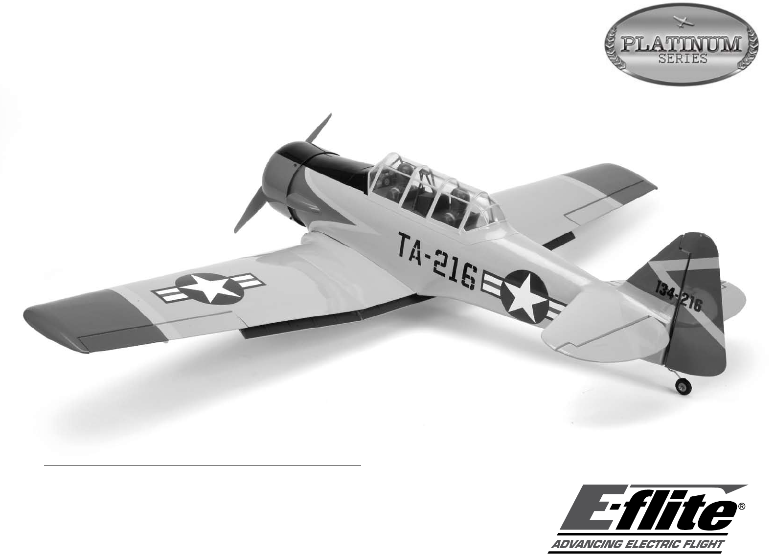
2 E-flite AT-6 Texan ARF Assembly ManualIntroductionE-flite’s AT-6 25e ARF is a superb scale replica of the legendary “Texan” trainer used by the U.S.
20 E-flite AT-6 Texan ARF Assembly ManualAileron Servo InstallationRequired PartsOuter wing panels (right and left) Servo w/hardware (2)3mm x 10mm se
21E-flite AT-6 Texan ARF Assembly Manual 5. Position the servo between the servo mounting block. Use a pencil to mark the locations for the servo m
22 E-flite AT-6 Texan ARF Assembly Manual 9. Route the lead from the servo to the opening for the flap servo. Use four 3mm x 10mm self-tapping scre
23E-flite AT-6 Texan ARF Assembly Manual 12. Use pliers to bend the pushrod 90 degrees at the mark. Use a pushrod connector to secure the pushrod w
24 E-flite AT-6 Texan ARF Assembly ManualFlap Servo InstallationOuter wing panels (right and left) Servo w/hardware (2)3mm x 10mm self-tapping screw
25E-flite AT-6 Texan ARF Assembly Manual 3. Using a ruler, mark the servo cover as shown using a pencil. 4. Position the servo so the arm is ce
26 E-flite AT-6 Texan ARF Assembly Manual 6. Position the servo between the servo mounting blocks. Use a pencil to mark the locations for the servo
27E-flite AT-6 Texan ARF Assembly Manual 10. Position the flap servo partially in the wing. Connect the clevis to the flap control horn. Plug the f
28 E-flite AT-6 Texan ARF Assembly ManualFixed Landing Gear InstallationRequired PartsWing center section Landing gear (right and left)1/8-inch wheel
29E-flite AT-6 Texan ARF Assembly Manual 4. Use a #2 Phillips screwdriver and four 3mm x 10mm self-tapping screws to secure the gear in the wing ce
3E-flite AT-6 Texan ARF Assembly ManualContents of Kit/Parts LayoutEFL4501 Wing SetEFL4501C Main WingEFL4501L Left WingEFL4501R Right WingEFL4502
30 E-flite AT-6 Texan ARF Assembly Manual 7. Slide the wheel onto the landing gear wire, then a final wheel collar. Use a 3mm x 4mm machine screw a
31E-flite AT-6 Texan ARF Assembly Manual 2. Remove the servo and drill the four locations for the servo mounting screws with a drill and 1/16-inch (1
32 E-flite AT-6 Texan ARF Assembly Manual 6. Remove the covering to expose the entire opening for the retract.Hint: Trim the covering about 1/16-inc
33E-flite AT-6 Texan ARF Assembly Manual 9. Apply a few drops of thin CA to each of the holes to harden the surrounding wood. 10. Use a #1 Philli
34 E-flite AT-6 Texan ARF Assembly Manual 14. Check that both linkages are an equal distance from the output of the retract servo. Adjust the linkag
35E-flite AT-6 Texan ARF Assembly Manual 17. Use a file to create a flat on the bottom of the landing gear wire. This provides a place to tighten t
36 E-flite AT-6 Texan ARF Assembly Manual 19. Slide the collar on the backside of the wheel up against the wheel and tighten the 3mm x 4mm machine
37E-flite AT-6 Texan ARF Assembly ManualPower System InstallationRequired PartsFuselage Hook and loop strapHook and loop tape 1. Make the connectio
38 E-flite AT-6 Texan ARF Assembly Manual 3. Use a hook and loop strap to secure the battery inside the fuselage. Use hook and loop tape between the
39E-flite AT-6 Texan ARF Assembly ManualWing InstallationRequired PartsWing panel (left and right) Wing center sectionWing tube (2) 1/4-20 x 2-inch
4 E-flite AT-6 Texan ARF Assembly ManualImportant Information About Motor SelectionWe recommend the E-flite® Power 25 Brushless Outrunner, 870Kv (EFL
40 E-flite AT-6 Texan ARF Assembly Manual 4. Carefully use the string to pull the Y-harnesses through the center section and out the opening in the
41E-flite AT-6 Texan ARF Assembly Manual 8. Untie the string from the plug ends of the Y-harness and tie it around the ends that will lead to the re
42 E-flite AT-6 Texan ARF Assembly Manual 11. Add (3) three inch extensions to the aileron, flap, and retract ports of the receiver. Plug the Y-harn
43E-flite AT-6 Texan ARF Assembly Manual 2. Use RC-56 canopy glue to attach the canopy to the fuselage. Use low-tack tape to hold the canopy in pos
44 E-flite AT-6 Texan ARF Assembly Manual 5. Use the following to paint the dummy radial engine.Optional Scale Cockpit InstallationRequired Parts(In
45E-flite AT-6 Texan ARF Assembly ManualFloor:Gun Ship GrayInstrument hood:Flat BlackRoll over support structure:Flat Black for the main support rods
46 E-flite AT-6 Texan ARF Assembly Manual 3. Glue the aft structure in place using Medium CA. You will want to make sure the canopy will fit on over
47E-flite AT-6 Texan ARF Assembly Manual 6. Glue the two pilots in place using Medium CA. They should be placed all the way back, almost against the
48 E-flite AT-6 Texan ARF Assembly ManualControl Throws 1. Turn on the transmitter and receiver of your AT-6. Check the movement of the rudder using
49E-flite AT-6 Texan ARF Assembly ManualCenter of GravityAn important part of preparing the aircraft for flight is properly balancing the model.Cautio
5E-flite AT-6 Texan ARF Assembly ManualNotes Regarding Servos and ESCWARNING: Use of servos other than those we recommend may overload the BEC of the
50 E-flite AT-6 Texan ARF Assembly ManualFlying Your AT-6 Texan ARFEnsure you have set the model up correctly and have the CG where it is stated in th
51E-flite AT-6 Texan ARF Assembly Manual2007 Official AMA National Model Aircraft Safety CodeGENERAL1) I will not fly my model aircraft in sanctione
11067© 2007 Horizon Hobby, Inc. 4105 Fieldstone Road Champaign, Illinois 61822 (877) 504-0233 horizonhobby.com E-fliteRC.com
6 E-flite AT-6 Texan ARF Assembly ManualDamage LimitsHORIZON SHALL NOT BE LIABLE FOR SPECIAL, INDIRECT OR CONSEQUENTIAL DAMAGES, LOSS OF PROFITS OR PR
7E-flite AT-6 Texan ARF Assembly ManualNon-Warranty RepairsShould your repair not be covered by warranty the repair will be completed and payment will
8 E-flite AT-6 Texan ARF Assembly ManualStabilizer InstallationRequired PartsStabilizer (right and left) 3mm x 10mm self-tapping screw (2)Stabilizer
9E-flite AT-6 Texan ARF Assembly Manual 4. Slide the stabilizer and tube in position in the fuselage. Note the direction of the control horn and tha
Related products and manuals for Air equipment E-flite AT-6 Texan 25 ARF
 (48 pages)
 (1 pages)
© 2020, manymanuals.com. All rights reserved. | 0.131 s |
 Manymanuals.com
 Manymanuals.de
 Manymanuals.fr
 Manymanuals.it
 Manymanuals.pl
 Manymanuals.cz
 Manymanuals.es
 Manymanuals-pt.com
Comments to this Manuals